Deutsch
  English
Visio P&ID Process Designer – Blogs

Blog | October 05, 2026
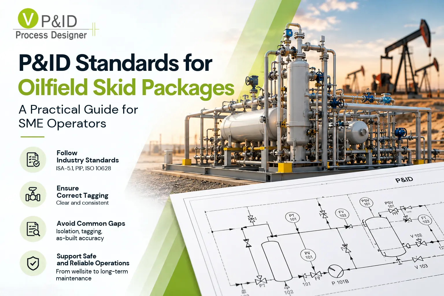
P&ID Standards for Oilfield Skid Packages: A Practical Guide for SME Operators
A choke manifold or a glycol dehydration skid rarely gets the engineering attention a refinery unit does. It ships pre-assembled, gets bolted onto a wellsite in a day or two, and is often installed from whatever drawing the equipment vendor emailed over. But the piping and instrumentation diagram (P&ID) for that skid still has to do the same job as one for a full plant: tell every downstream user — the technician isolating a pump five years from now, the contractor doing a tie-in, the safety officer reviewing a permit-to-work — exactly what's connected to what, and how to shut it down safely.

Blog | July 23, 2026
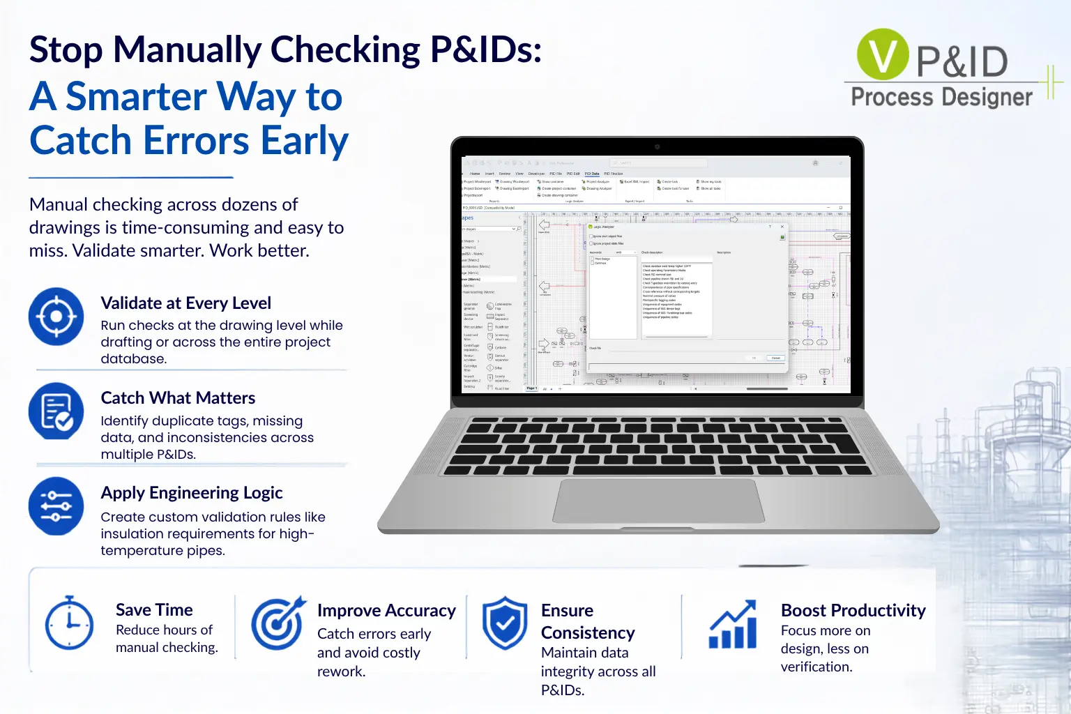
Stop Manually Checking P&IDs: A Smarter Way to Catch Errors Early
On most projects, P&IDs don’t exist in isolation. You’re usually working across dozens of drawings, sometimes 10, sometimes 50 or more, all part of the same system.
And at some point, someone must check them. Typically, that means going drawing by drawing, looking for duplicate equipment tags, repeated valve numbers, missing data, or inconsistencies in naming. It’s a necessary step, but also time-consuming and not particularly reliable at scale.

Blog | July 10, 2026
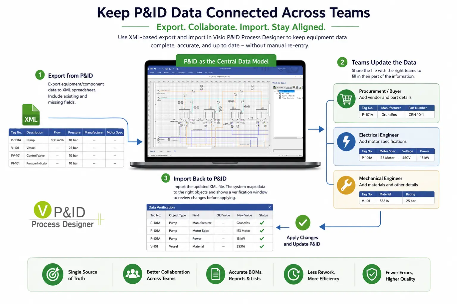
Turning P&IDs into a Shared Data Model Across Engineering Teams
When working on a P&ID, you rarely have all the information upfront.
You might define a pump with flow and pressure requirements or place a vessel with design conditions, but details like manufacturer, part numbers, or motor specifications often come later, from different teams.

Blog | May 28, 2026
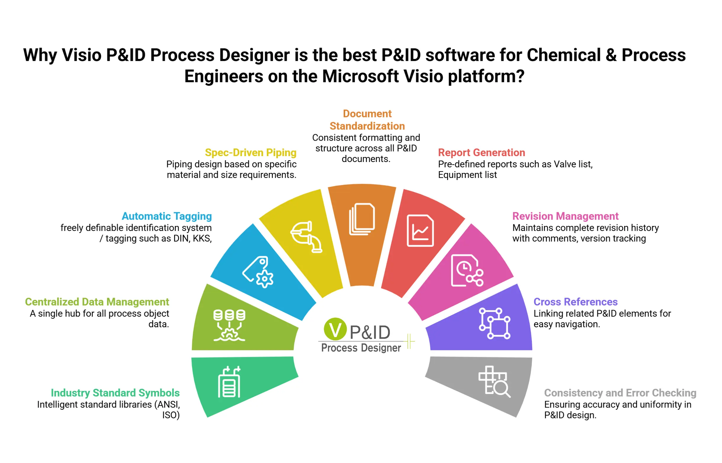
Why process engineers prefer Visio P&ID Process Designer over plain Microsoft Visio
For process engineers already working within Microsoft ecosystem, Visio P&ID Process Designer is compelling because it fills the biggest gap in native Microsoft Visio: turning simple diagrams into intelligent engineering documents.
Standard Microsoft Visio is effective for creating drawings. Visio P&ID Process Designer adds the engineering functionality that process engineers need.

Blog | Apr 15, 2026
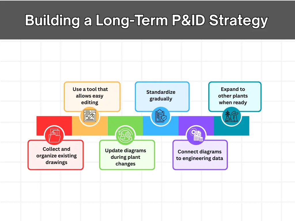
A Practical Approach to Modernizing P&IDs Workflows
In every process plant, Piping & Instrumentation Diagrams (P&IDs) remain one of the most critical engineering documents throughout the entire lifecycle of the facility. They provide a detailed representation of process equipment, piping systems, control loops, and instrumentation required to operate the plant safely and efficiently.

Blog | Sep 03, 2025
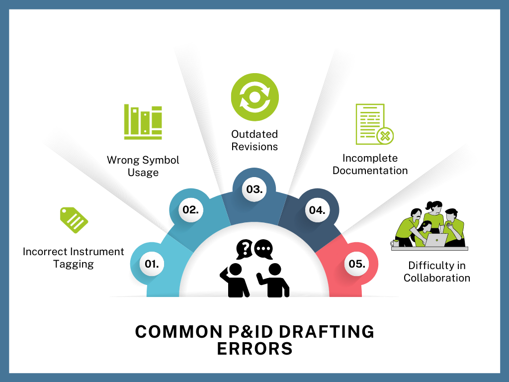
The Hidden Cost of P&ID Errors: How Small Mistakes Lead to Big Project Delays and Safety Risks
In the world of process engineering, Piping and Instrumentation Diagrams (P&IDs) are more than just technical drawings — they are critical blueprints that guide engineering design, construction, operations, and safety procedures. Yet even minor mistakes in these diagrams can lead to major consequences: missed deadlines, compliance violations, equipment failures, or worse — safety hazards.
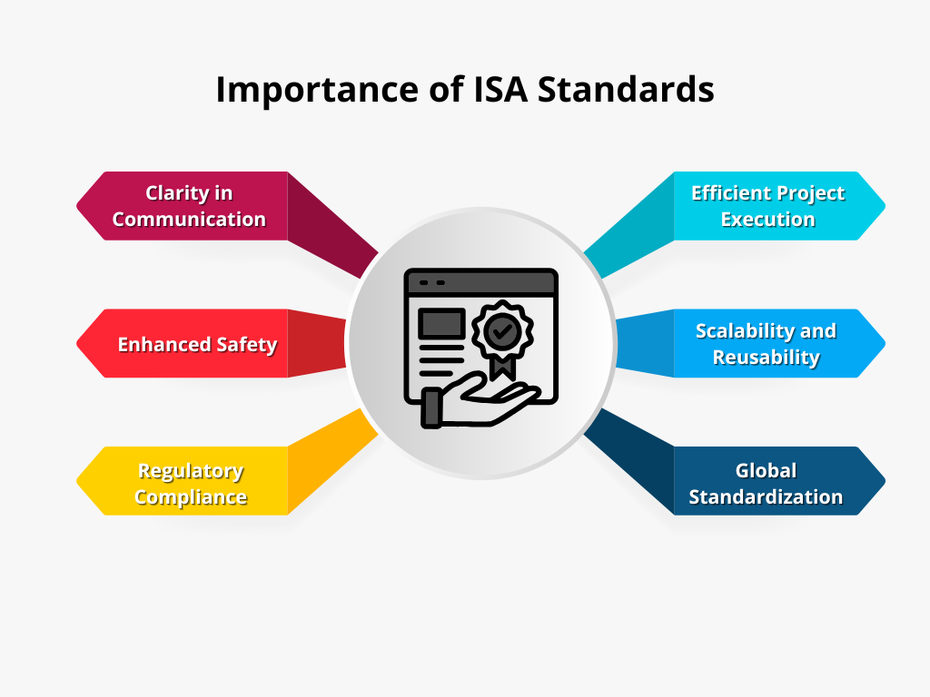

Importance of ISA Standards in P&ID Design
In the field of process and instrumentation Design, precision and clarity are paramount. Engineers rely on standardized methods to communicate their designs effectively and to ensure seamless collaboration across teams, industries, and geographies.
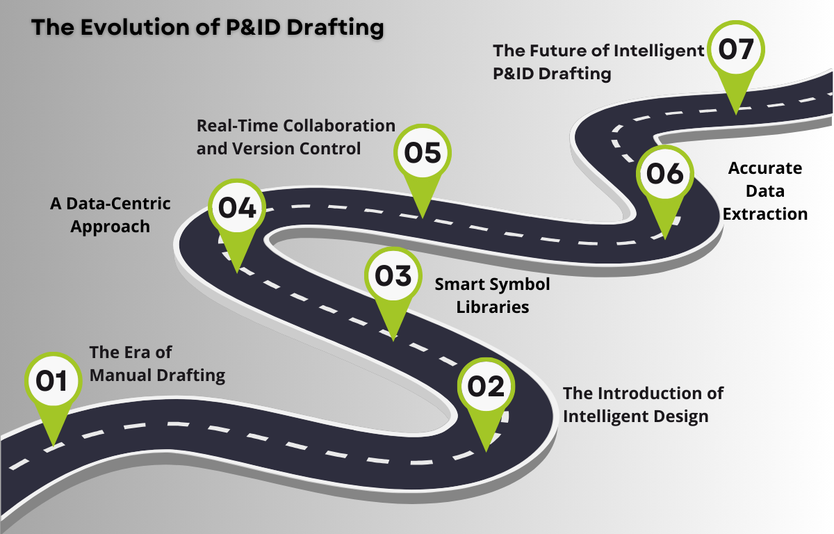

The Evolution of P&ID Drafting: From Traditional Tools to Intelligent Design
The world of Piping and Instrumentation Diagrams (P&ID) has undergone a remarkable transformation over the years. What once required painstaking manual effort has now become an intelligent and streamlined design process, thanks to advancements in engineering tools and technology.


Introduction to Intelligent P&ID Tools
In the realm of engineering and industrial design, Piping and Instrumentation Diagrams (P&IDs) & Process Flow Diagrams (PFDs) serve as fundamental blueprints, outlining the intricate networks of piping, instrumentation, and process flow within a facility.